
Neutral Grounding Resistors
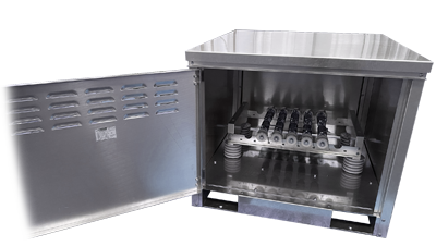
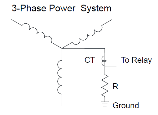
Neutral grounding resistors ground power systems by connecting a resistor between the power-system neutral and ground. They limit ground-fault currents while preventing transient over-voltages and enabling fault detection and measurement.
Time & temperature ratings
- 10-second rating — relay-protected systems, max 760 °C rise
- 60-second rating — multiple outgoing feeders, max 760 °C rise
- 10-minute rating — extended fault processes, max 610 °C rise
- Extended-time rating — faults beyond 10 min (avg 90 days/yr), max 610 °C rise
- Continuous rating — fault conditions 90+ days/yr, max 385 °C rise
How to specify
- System voltage or line-to-neutral voltage
- Fault current
- Time rating
- Enclosure type (open, indoor or outdoor)
- Options: current transformer, elevating stand, special finishes, seismic, disconnect switch
Standards & construction
- Designed and factory-tested to IEEE Standard 32
- Conform to Seismic Zone 2 unless otherwise specified
- Mill-galvanized or ANSI 61 grey finishes
- Stainless-steel edgewound resistors and porcelain standoff insulators
- Completely pre-assembled before delivery
Related products
Get a quote
Ready to spec your resistor?
Send us your ohms and watts — or your drive, voltage and duty cycle — and our engineers will build a reliable, economical solution.